

Power indicator: A green LED that lights when power supply is normal.
Status warning LED: Red LED indicating fault or status changes:
LED is off under normal operation.
If EN is not connected to COM, red LED remains ON.
If the motor’s Hall sensors fail, the red LED will blink once then stop.
If the motor stalls, red LED will blink 5 times then stop.
Signal & control terminals:
PWM: Connect PWM positive to PWM terminal and negative to COM. Use a PWM signal of 100 Hz–1 kHz with +5 V amplitude; adjust the duty cycle from 0 to 100% to control speed.
Ve (Voltage control): Adjust the Ve terminal voltage (0–5 V) to control motor speed from 0% to 100% (PWM or Ve can be used; PWM is recommended for higher speeds).
BK (Brake control): Controls the motor brake — if BK is floating or connected to V+, motor runs normally; when BK connects to COM, brake engages → motor stops and red LED turns on.
FG (Frequency generator): Outputs pulses proportional to motor speed — you can measure frequency (F) and compute RPM using: RPM = F ÷ N × 60, where N = number of pole pairs.
DIR (Direction control): Controls rotation direction — DIR pulled to COM → forward rotation; DIR floating or to V+ → reverse rotation.
EN (Enable control): Motor enable signal — when EN = COM, motor runs; when EN is floating or V+, motor stops.
Phase outputs (U, V, W + driver power): Connect to the BLDC motor phases as per wiring diagram.
Wiring diagram: follow the included schematic for proper wiring.
Speed measurement method: Measure the FG output frequency and calculate RPM with the formula above.
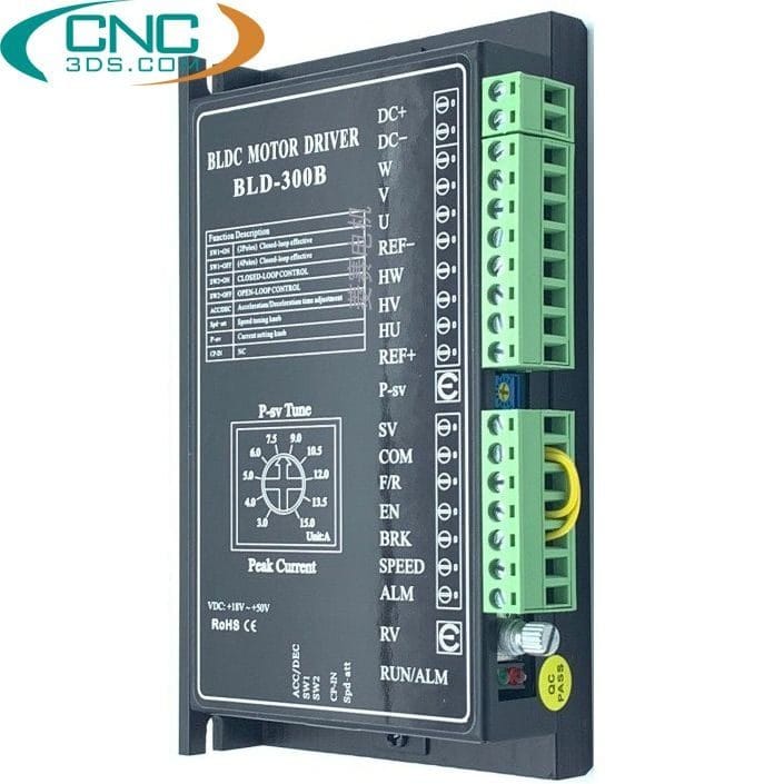
BLD-300B Brushless DC Motor Controller 24/36/48V
1.320.000 ₫
- Model: BLD-300B 24/36/48V
- Current rating: 15 A
- Voltage: 18–60 VDC
- Max motor power: 300 W
- Compatible motor: Brushless DC (BLDC) motor